
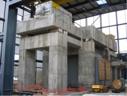
Our firm was recently engaged by a major power plant operator in West Java to conduct a comprehensive investigation of an in-service steam-turbine-generator unit. The assessment was prompted by several operational concerns, including anomalous vibration readings and visible structural damage. Our team traveled to the very west region of Java during the November rainy season to carry out the on-site investigation. In this post, we share an overview of the methodology and approach employed in this project.
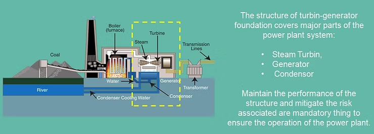
Foundation of Dynamic Equipment
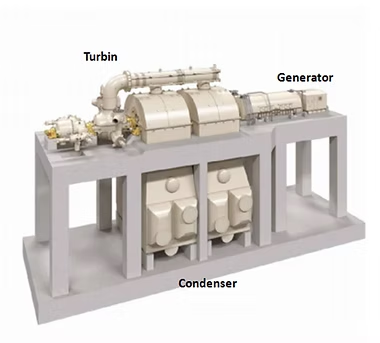
Foundations supporting dynamic equipment differ fundamentally from conventional foundations, as they must accommodate not only static loads but also the dynamic loads generated by vibrating machinery. Such equipment may include compressors, pumps, turbine-generators, and other rotating or reciprocating machinery. To ensure satisfactory foundation performance under these dynamic conditions, three main design principles should be observed:
1. Natural Frequency of Structure and Resonance
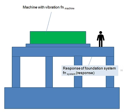
A foundational step in dynamic foundation design is establishing the natural frequency of the structure, as this governs its dynamic behavior and proximity to the resonance zone. The natural frequency of a structure is a function of its stiffness (k) and mass (m): greater stiffness increases natural frequency, while greater mass reduces it.
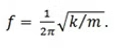
Structural natural frequency can be estimated using simple approach using formulas referenced in ASCE and SNI standards, summarized in the table below.
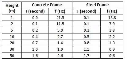
To avoid resonance, the structure’s natural frequency should fall outside the operating frequency range of the machine, specifically below 0.8 times or above 1.2 times the machine’s operating frequency. A typical steam turbine generator (STG) or combustion turbine generator (CTG) operates at 3,000–3,600 rpm, equivalent to 50–60 Hz. Referencing the table, typical concrete framing systems exhibit natural frequencies well below this range (approximately 0.6–21 Hz), placing the foundation in the “low-tuned” zone. Within this zone, a lower structural natural frequency is generally favorable, as it reduces dynamic transmissibility and improves overall dynamic performance.
2. Rule of Thumbs: Weight Control
As established, typical STG foundations fall within the low-tuned zone, where a lower structural natural frequency is desired. Since natural frequency is inversely related to mass, this implies that increasing the mass of the structure is an effective means of achieving the desired dynamic performance.
In line with this principle, ASCE guidelines provide the following rules of thumb for proportioning foundation mass:
- The tabletop concrete weight should not be less than the total machine weight.
- The self-weight of all vertical structural elements (columns and walls) supporting the tabletop should be 40 to 60% of the combined weight of the machine and tabletop.
- The base mat weight should not be less than the combined weight of the machine and tabletop.
- The total foundation concrete weight (tabletop, columns/walls, and base mat) should not be less than 3.5 times the machine weight.
While these rules of thumb do not, on their own, guarantee adequate foundation performance, our experience across multiple projects has shown them to be a reliable and effective starting point for designing robust foundations for dynamic equipment.
3. Structure Response and Serviceability
Two categories of serviceability must be verified in the design of foundations for dynamic equipment:
- Static stability, which ensures proper bearing capacity and alignment is maintained throughout machine operation.
- Dynamic serviceability, which ensures the foundation does not experience resonance or excessive vibration amplitude under normal operating conditions.
Serviceability limits are typically specified by the machine manufacturer and vary across manufacturers. In our experience, these manufacturer-imposed limits are often more stringent than the structural requirements needed to withstand machine loads alone, frequently resulting in a larger foundation size than would otherwise be dictated by structural considerations.
To develop a representative model for both static and dynamic analysis, a minimum dataset must be collected, comprising: geotechnical and foundation data, machine static and dynamic load information, and detailed foundation layout drawings.
Basic Load of TG System
The TG system is defined by two fundamental dynamic loads:
- Turbine unbalance load
- Generator unbalance load
These values are typically provided by the equipment manufacturer and form the basis for subsequent dynamic analysis. Two types of dynamic analysis are generally performed to assess foundation performance.
Frequency Analysis (Modal / Eigenvalue Analysis)
Frequency analysis is used to determine the natural frequency of the structural system. This analysis yields key dynamic characteristics, including natural frequencies, mode shapes, and modal participation mass ratios, which are used to verify the structure’s frequency separation from the resonance zone. Most manufacturers require that the structural frequency remain outside a band of ±20% of the machine’s operating frequency.
However, a tabletop foundation is a complex structural system exhibiting numerous global and local modes. Frequency analysis alone is therefore insufficient to confirm that the foundation will not experience excessive vibration, as additional modes may exist in close proximity to the resonance zone. For this reason, a forced vibration (steady-state) analysis is also required.
Forced Vibration Analysis
This analysis calculate the peak steady-state foundation response (displacement, velocity, acceleration) for harmonic unbalance load applied at each forcing freqency. This is a frequency domain analysis where a harmonic load ranging from -20 % to +20% of the machine frequencies are applied.
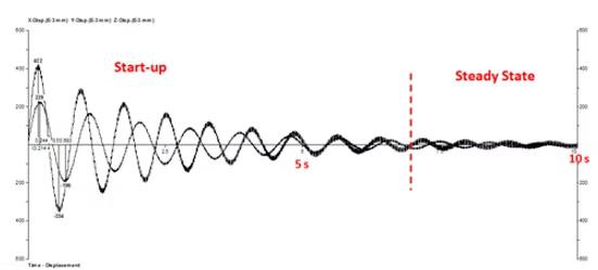
Time history method is one common approach that can see the response of the structure from start-up until steady-state phase achieved. It is noted that during start-up a relatively large vibration occur however it lasted only several seconds before the steady-state phase achieved.
by Wyat team, 2020.
Leave a Reply